Abrasive Wear Mechanism

Abrasive Wear in Bulk Material Handling

In the field of construction machinery and bulk material handling systems the main cause of equipment failure is the high level of wear and as a result a downtime of the production. This wear occurs especially in the handling of highly abrasive bulk materials and powders. For instance, hard rock materials like granite or minerals like iron ores and blast furnace slag. The wear is usually due to the function of the conveyor or construction machine of handling the bulk material. Therefore it cannot be completely avoided. Hence,  the engineering focus is on the optimal design of the equipment geometry to reduce wear conditions and secondly a suitable selection of wear resistant liners.  In order to successfully manage this, basic knowledge about the wear mechanisms is necessary. Therefore, the next paragraph shows a brief overview of the relevant wear mechanism.

Wear Mechanism

The complexity of the wear usually results from the superposition of different mechanisms. In general,  there are four main groups of wear mechanism: Abrasion, Adhesion, tribo chemical reaction and surface fatigue. All of these wear mechanism can occur also in bulk material handling applications depending on the environment conditions. However,  the abrasive wear is by far the most dominant wear mechanism in bulk material handling. It consists of the subgroups of abrasive impact wear (erosion) and sliding wear.

Wear Mechanisms
Figure 1: Overview of Main Wear Mechanism in Bulk Material Handling

The following Figure 2 shows a systematic drawing of a transfer station, a common industrial application, in bulk material handling. A belt conveyor transports the bulk material with a constant velocity. The material stream leaves the belt conveyor and hits against an impact plate before it falls down on a transfer chute below. Afterwards, the materials stream slides further down the chute. In this example zones of impact wear and sliding wear exist. Both of these cases are representative for wide range of applications in industrial praxis. Nevertheless, it should be noted that in practice often both types of wear can occur simultaneously. But also one of the mechanisms is usually dominant. In the next section we will take a closer look to the wear mechanisms seperately.


Abrasive Sliding Wear

Figure 3a shows a zoom into the contact zone of material stream on the chute. Thereby only the lowest layer of particles is in contact with the chute. The material stream slides down the chute with a sliding velocity vs. As a result of the contact and relative movement between the particles and the chute wear occurs. To quantify the occuring wear Figure 3b shows even closer zoom to a single particle in contact with the wall.

Sliding Wear on a chute
Figure 3a: Sliding zone between bulk material and chute
Sliding Wear of a single particle
Figure 3b: Zoom to single particle sliding on the chute

The analytical description of the volume loss due to abrasive sliding wear is based on the experimental investigations on solids by Archard. The wear is both proportional to the normal force, Fn, and the distance, Δs, covered. Furthermore, it is inversely proportional to the hardness, H, of the wear surface of the softer contact partner. Hence, the wear or in other words the volume loss is calculated by:

Archard equation

The factor K is a dimensionless coefficient that depends on the material properties of the contact partners and the conditions of the contact. Further simplified K/H is often given as single variable, called ka,V (in mm³ / Nm). The calculation is reduced to:

Archard equation simplified

In this case, the wear factor ka,V takes into account a large number of properties of the contact parameters that influence the wear. In gerneral, this parameter has to be determined by wear experiments. Here you will find an overview of such experiments.

Abrasive Impact Wear

Figure 4a shows a zoom into the contact zone of material stream on the impact plate. The material stream hits the impact plate with a impact velocity under a specific impact angle. As a result of the contact and relative movement between the particles and the impact plate wear occurs. To quantify the wear occuring on the impact plate Figure 4b shows even closer zoom to a single particle just before in contact with the wall.

Impact Wear Material Stream
Figure 4a: Impact zone between bulk material and impact plate
Impact wear of single particle
Figure 4b: Zoom to single particle impacting the impact plate

Here, mp is the mass of the particle and vi is the impact velocity of the particle. The angle α is the angle between the direction of movement of the particle and the surface The analytical description of the volume loss due to abrasive impact wear for ductile materials is based on the experimental investigations by Finnie. The wear is proportional to the mass of the particles (or the acting force) and the square root of the impact velocity. Furthermore, the impact wear is highly influenced by the impact angle between the movement direction of the particle and the impact plate. Hence, a simplfied model can be used to describe abrasive impact wear on ductile materials by:

Finnie equation

Like in the sliding wear a impact wear coefficient kf,V (in mm³ / Nm) exists. This coefficient takes into account a large number of properties of the contact parameters that influence the wear.

Influence of the impact angle

The influence of the impact angle is discribed by the function f(α) :

Finnie equation Angle relation

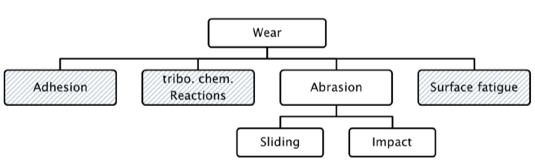
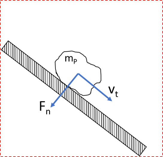
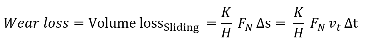
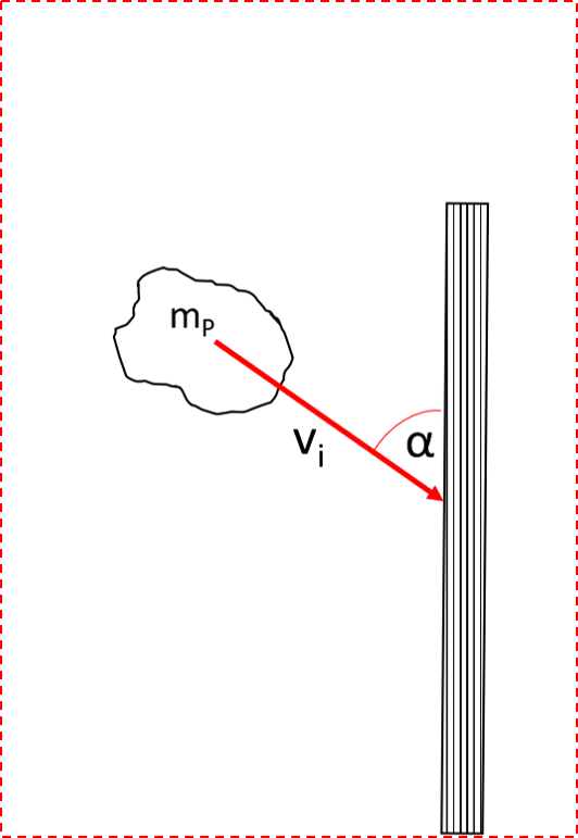
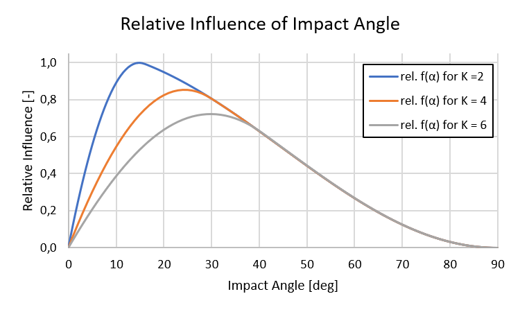
As a result of plotting the function f(α) over the possible impact angles, the influence of the impact angle becomes more clear (Figure 5). In Gerneral, the volume loss of the impact is more critical at smaller impact angles than at larger impact angles because the individual grains make a cutting motion in the base. Furthermore, the critical impact angle of the highest wear depends on the ratio of the normal force to the tangential force. This ratio can be simplified expressed as a variable K = 1 / μ. Hereby, μ is the coefficient of friction between the bulk material and the liner material. The following diagram shows the relative influence of the variable K on the critical impact angle and therefore on the wear. For ductile liner materials the critical impact angle is usually between 15 deg and 35 deg.

In contrast, the critical impact angle for brittle liner materials is usually at an impact angle of 90 °. This means that the impact of a bulk material stream normal to the surface creates a very high level of wear on brittle liners. For this reason, the presented Finnie Model is only valid for ductile materials.

Finnie angle relation
Figure 5: Influence on the impact angle on the relative impact wear

The diagram shows that the value of the critical impact angle depends on the K value. This value K is representative for the combination of bulk material and wall liner material. Hence, it has to be determined for each specific application case. As a result of this knowledge an optimal impact wall geometry can be designed.